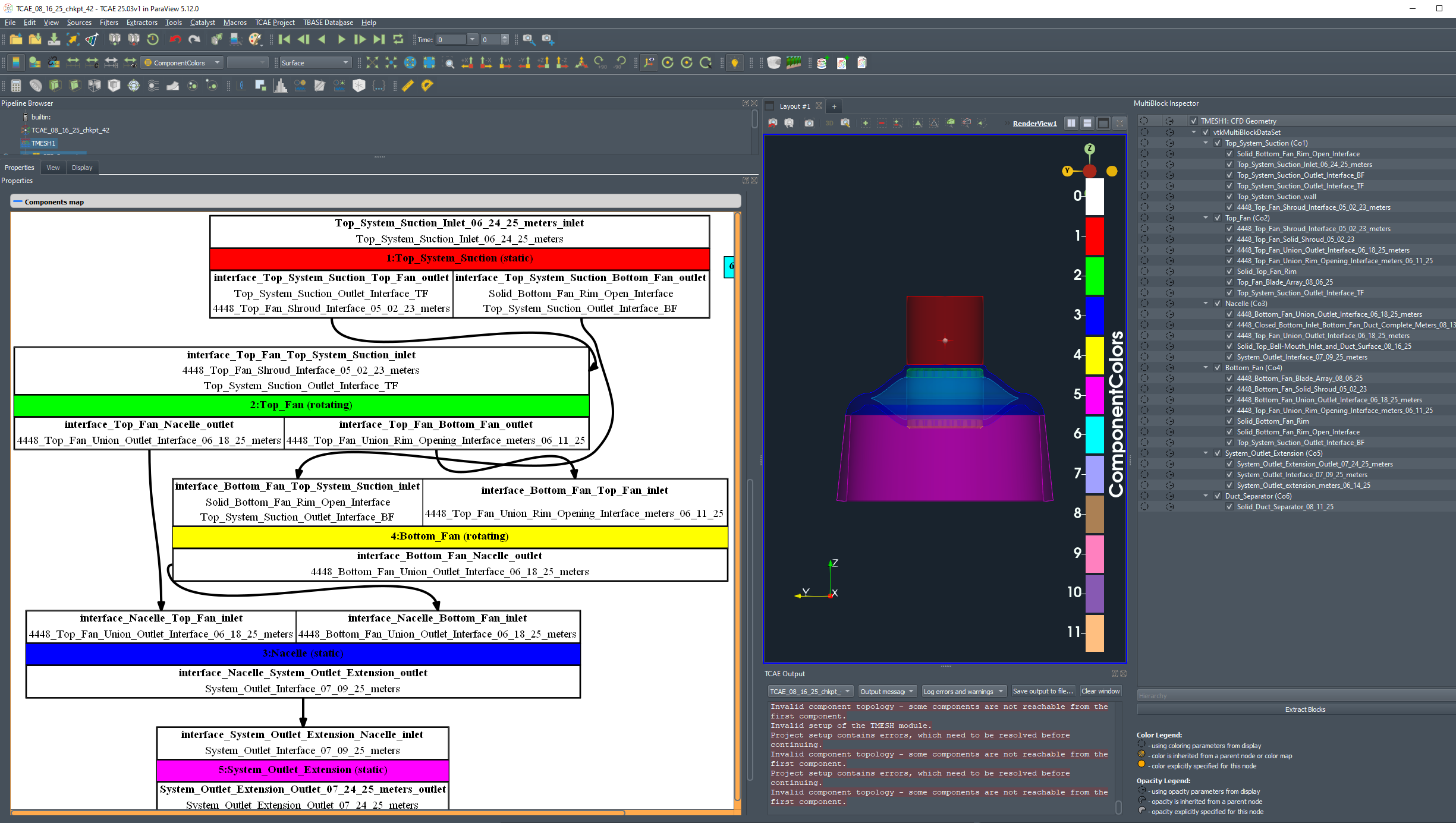
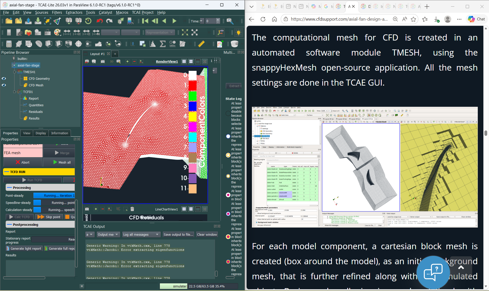
Hi,
I'm a new user of TCAE-Lite.
I've setup a pump case and the "check" button says the case has been setup correctly. However it fails to mesh.
The same error occurs when running the f1 tutorial case.
Any advice would be appreciated,
Thanks,
Tom
Hi,
I'm a new user of TCAE-Lite.
I've setup a pump case and the "check" button says the case has been setup correctly. However it fails to mesh.
The same error occurs when running the f1 tutorial case.
Any advice would be appreciated,
Thanks,
Tom
Hello,
I found you have changed the Spitfire TCFD example few versions ago so as it applies 1.5AoA - or -1.5 It does not matter actually in this scope - by rotating velocity vector and aiming to get it rotated as expected by setting forces axes rotated in Runtime evaluated quantities, so this should apply to the final report. I've simplified the example - to get faster results - and found that in the report forces are never rotated as expected despite that Coefficients are rotated, you can test this by changing the Forces in Runtime evaluated quantities to 0,0,1,1,0,0 in the example and see that only Coefficients are changed in the report.
Tested on TCAE 25.03v1
Hi everyone,
I woud like to export the relative velocity URel magnitude, instead of the absolute velocity U magnitude, in the interfaces files created by TCAE in ../stationnary/postProcessing/interfaceName/0/interfaces.csv. I tried to change the file ./stationnary/system/interfaces. fun by replacing magU by magURel in the list of fields per interface but it did'nt work... How can I do it ?
Thanks in advance !
Zacharie Prigent
TCAE-Lite is designed for those with limited budgets.
Over 50 man-years of consistent development on top of open-source condensed in unlimited software at the cost of a daily cup of coffee.
https://www.cfdsupport.com/tcae-lite.html
hashtag#CFD hashtag#Simulation hashtag#FluidDynamics hashtag#FlowVisualization
I am looking to simulate the power output of an in pipe axial turbine, I don't have any experience in CFD simulations and I've decided to brake down the project into 3 parts, first I am going to simulate just the pipe in which the turbine is going to be housed, then a static state with the turbine in the pipe, and finally setup the rotation of the turbine.
I've made a quick 3D model of the pipe and I tried copying the setup from the pipe example, I ran into a problem where the mesher consumes all the available RAM on the computer and locks it up, I assume the STL mesh has a hole somewhere but I couldn't find it, I've had issues before with glitches in STL meshes made in Rhinoceros 3D, the modeling program I used, so I decided to recreate the pipe example with the STLs from the example, and that meshed successfully, but I got an error in the TCFD part "TCFD calculation failed. Please consult the chapter 'Rescue list' in the TCAE Manual for possible reasons of the failure.", I couldn't find the Rescue list chapter in the manual online.
Also the TCAE Output gives this error:
"Application decomposePar failed.
For detailed information check error log at: "C:\Users\Name\Desktop\CFD Test\CFD_test\simulationRun1\TCFD\logRun\solve-err-decomposePar-stationary-1.log"".
And in that log file is:
"--> FOAM FATAL IO ERROR:
Cannot find patchField entry for Co1_pipe-wall_wall
file: C:/Users/Name/Desktop/CFD Test/CFD_test/simulationRun1/TCFD/stationary/0/nut/boundaryField from line 32 to line 54.
From function void Foam::GeometricField<Type, PatchField, GeoMesh>::Boundary::readField(const Foam::DimensionedField<TypeR, GeoMesh>&, const Foam::dictionary&) [with Type = double; PatchField = Foam::fvPatchField; GeoMesh = Foam::volMesh]
in file /opt/OpenFOAM-dev/src/OpenFOAM/lnInclude/GeometricBoundaryField.C at line 184.
FOAM exiting"
Attached is a rough diagram of how will the setup work.
I don't have an idea what to try next, and would be thankful for any assistance.
I have just installed v24.10 of TCAE-Lite. Initially I installed under Linux, sicne that is where I would really like to use the software. Having downloaded the pipe tutorial I load the case and get this message "Project configuration not fully valid according to TCAE-Lite 24.10 and may have been auto-corrected." When I try to run, I get a message that the caluclation cannot be started, and that the project contains some problems. Upon using the check option, it says that there is no geometry loaded for solid component 1. The stl file does exist in commonData\TMESH\imported and I can load it into ParaView with no issues.
So I then tried installing under Windows. In this case it does not complain about the geometry. However, when I try to run I still get a failure, which is "Failed to execute "netgenSTLMesh" (error 2)." It asks me to check an error log (mesh-err-07-netgenMesh-component1.log), but this file does not exist (there is no netgenmesh log file, and the mesh-err-07 file is called mesh-err-07-mergeMultiMeshes.log.
Can anyone provide details as to why the FEA meshing fails under Windows, and why the geometry does not work under Linux?
Hello, I am very new to CFD and simulations, I am trying to simulate the power output of a kaplan hydro turbine. I have made the geometry, but when I try to mesh it, after 15 minutes it fails. Is there any function in TCAE that I can use to check the mesh, I think it might not be water tight, but I don't know where. Also, the setup check passes without errors.
If you need any more information, please let me know.
Thank you in advance.
Hello,
I tried to run the benchmark cases NACA0012 and now I am at TCAE module. I have noticed that the running time of TCAE is long and I want to accelerate it but I haven't found places to set the number of processors. Is that means the module cannot be computed in parallel? By the way, no my CPU utilization is low but memory is full.
Thanks for help.
Hello everyone,
I have questions about the calculation of circumferential angles circA by TCAE.
I have understood that, if a surface is oriented in the radial direction, circA on this surface will be the angle between the tangent and the velocity in the radial/tangential plane. According to graphical representation of the manual, circA shoud be positiv when the projection of the velocity in the radial/tangential plane points out (of the cylinder in the picture), and negativ when it points in.
Let's imagine that we are on a surface radially oriented where some back flow occurs and that the absolute velocity has a circA > 90Β° when there is no back-flow. In most of the cells of the surface, circA points out of the cylinder (90Β° < circA < 180Β°), but when back-flow occurs, circA points in the cylinder (-180Β° < circA < -90Β°). Thus, there are positiv and negativ values of circA at the same time, isn't it ? Therefore, because the circA are either > 90Β° or < -90Β°, in the in the interfaces-final.csv file in simulationRun1/TCFD/stationary/postProcessing/surfaceName/0/ folder, it seems to me that surface averaged value of circA is distorted.
I had this reflection because I find particularly high values of circA on some surfaces of my simulations.
Could someone confirm my interpretation ? Or explain me why it isn't true ?
Besides, does someone know how to visualize circA angles on Paraview after a calculation ?
Thanks in advance !
Zacharie
TCAE module selection buttons have disappeared. How to restore them?
Thanks in advance.
~ David
Evidently I've clobbered my TCAE installation because the module selection buttons are now missing. Re-installing TCAE had no effect. How to restore them? Thanks in advance.
~ David
Using cutting-edge CFD and CAA techniques, we conducted a comprehensive analysis of an axial fan's acoustic performance! ππ
Key insights:
Evaluated sound pressure level (SPL), power spectral density (PSD), and directional characteristics ππ
Reconstructed acoustic signals from simulation results π§
Visualized fluid flow with velocity contours and vorticity ππ¨
Leveraged the powerful TCAE simulation environment π»π§
π PDF: https://www.cfdsupport.com/download/AXIAL-FAN-ACOUSTIC-BENCHMARK-TCAE-CFDSUPPORT.pdf
π Full Case Study (download available): https://www.cfdsupport.com/axial-fan-acoustic-benchmark.html
This advanced workflow provides valuable insights for noise reduction, acoustic design, and optimization of fan systems in industries like HVAC, automotive, and aerospace! ππβοΈ
Interested in applying these techniques to your projects? π€ Contact us to learn more! π©
#CFD #CAA #AcousticAnalysis #AxialFan #NoiseReduction #AcousticDesign #TCAE
Hello sir
i had gone through your webinars and various papers. recently i had read your published information regarding <TCAE-CFDSUPPORT-ACOUSTIC-BENCHMARK-PROPELLER-DJI9450> . I want to try simulation on same propeller can you please provide me cad model for dji9450 propeller that you had used in Ur simulation.
THANK YOU
What is
your recommended tool flow from Solidworks to TCAE that preserves surface names
(inlet, outlet, walls etc) ?
My understanding
is that unfortunately Solidworks does not preserve surface names when
exporting the model as an STL file and exporting surfaces as separate STL files
will produce non-conformal vertices.
Does one
need to go through a third-party mesher ? I believe the Solidworks .step export
preserves surface names. Is the recommended tool flow to go through a package
such as Salome to create separate (but conformal) stl surface meshes ?