CFD, OpenFOAM, ...

CFD simulation for industrial fan
Igor Volodin
Hello everyone!
I need to create fan curve of my model. I created a model, mesh for my model that you can see in my attached screenshot. My model consist of fluid zone, inlet and outlet surfaces, solid impeller and rotation zone above impeller. I created interface between rotation zone and fluid zone and made my rotation zone as frame motion ‘cause I try to calculate my task as steady.
I’m trying to figure it out how to set my boundary conditions, what type should they have? My first try was that i set pressure inlet at 0 and pressure outlet at 0 Pa. But my monitors looks terrible. Mass flow rate isn’t stable and I don’t understand when i must to stop my calculation. If you can, I will be very thankful for explanation. Not almost step-by-step, but if You give me a few advices, I will be very grateful.
Mr. Pirkl, thank you for your answer by email!
I’m creating this topic for further discussion.
In Your letter, You answered, that I need to sweep through different outlet pressures.
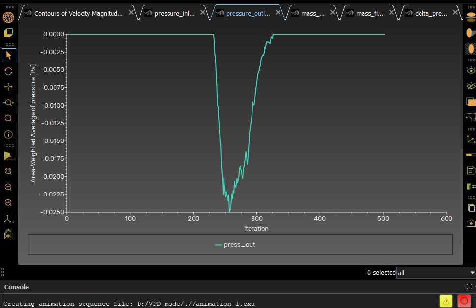
I’ll try to explain my situation, because I can’t sent my examples now. I’m setting inlet/outlet pressures to zero. Then I’m starting to aiming difference between outlet and inlet like dP=P_out-P_in and in my calculation, my flow rate decrease, inlet pressure increase but my outlet pressure starts decrease in one moment like this (found screenshot). Should I check my pressure not on inlet/outlet surfaces and on middle surface of my channels?
Login To Post Your Comment