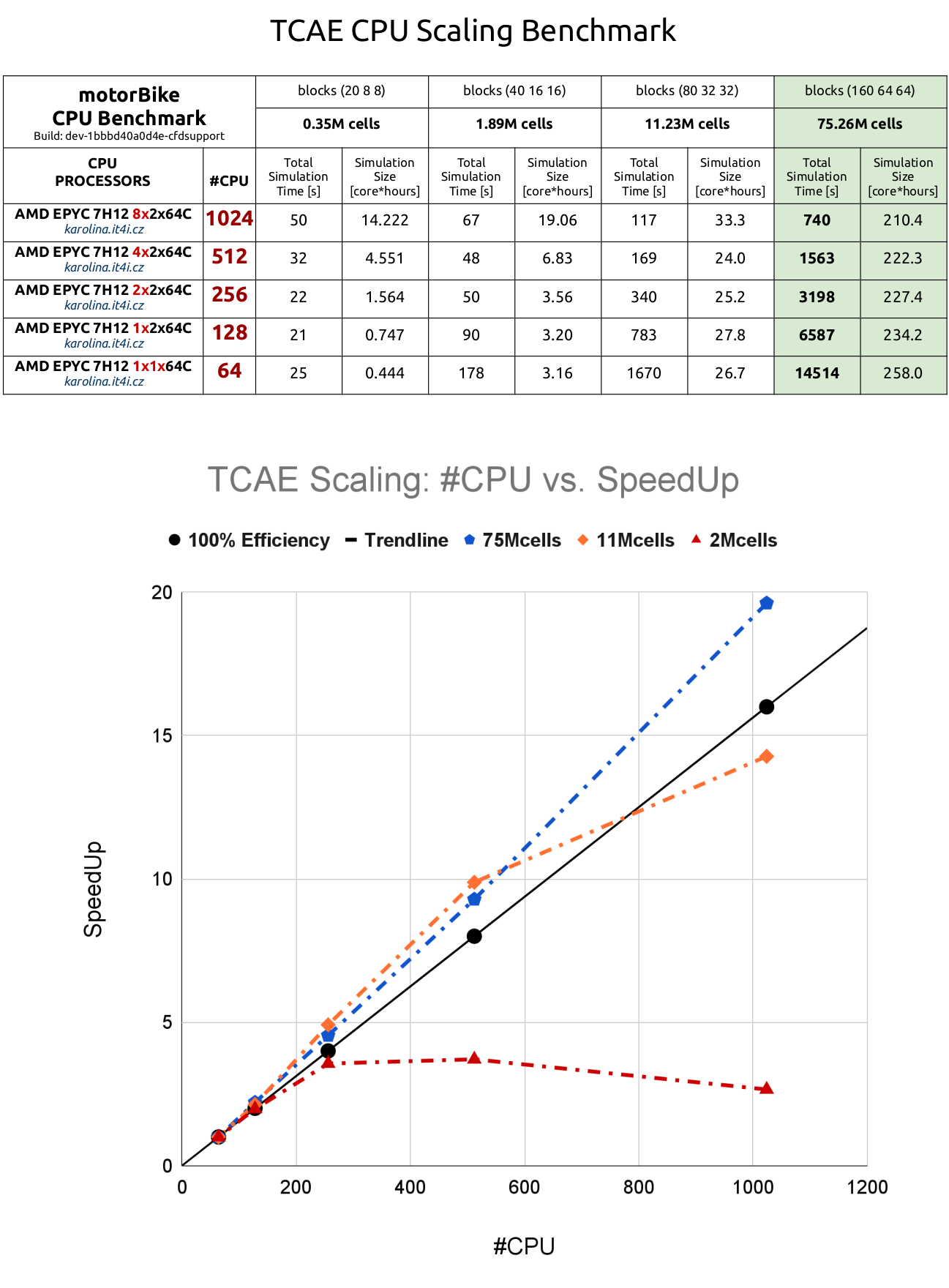
We have updated our publicly accessible benchmark, based on the well-known motorBike tutorial from OpenFOAM. It allows anyone to evaluate and compare CPU performance using a standardized test case. The benchmark is both transparent and repeatable, making it suitable for a wide range of users, from hobbyists to professionals. The test includes four mesh sizes. 0.35 million, 1.9 million, 11 million, and 75 million cells (with the largest requiring around 60 GB of RAM). The setup uses default parameters, and though CFD SUPPORT recommends either their own blueSolver or participants can also use the standard simpleFoam solver. This newly updated CFD benchmark includes a new CFD scaling study that shows the TCAE software CPU scaling on 64, 128, 512, and 1024 simulation cores. It extends our older Kaplan turbine parallel scaling benchmark.
CPU speed & scaling benchmark updated!
New Scaling Study
All Posts
Question Regarding Thrust & Torque Values in DJI 9450 Benchmark Report
- Post By 稚樺 王
- 9 months ago
- Post Type Public
Hello everyone,
We are a team of university students currently working on a project to replicate the CFD simulation of the DJI 9450 propeller. First of all, we would like to thank the content creators for the excellent "Acoustic Benchmark Propeller DJI 9450" study. It has been an invaluable resource for our work.
As we try to reproduce the simulation results, we've encountered some confusion regarding the benchmark target values and would be very grateful for any clarification from the community or the official team.
Issue 1: Discrepancy Between Two Reported Results
We have been referencing two main documents:
[1] The formal PDF research report (Acoustic Benchmark of DJI 9450.pdf).
[2] The web page report, available at: https://www.cfdsupport.com/download/report/DJI-9450-Propeller-Benchmark/tcfd/TCFDReport.html
We noticed a significant difference in the thrust and torque values at 6000 RPM between these two sources. Specifically:
* The PDF Research Report [1] lists a target Thrust of 4.256 N and a target Torque of 0.066 N·m.
* The Web Page Report [2]shows a computed Thrust of 3.438 N and a computed Torque of 0.058 N·m.
Furthermore, the simulation result graph in the PDF report (approx. 4.2 N) also differs from the web page report's result (3.44 N).[1] We suspect this might be due to differences in mesh density. Could anyone confirm if this understanding is correct, and which set of values should we consider the definitive target for our validation?
Issue 2: Question About the Source of the Benchmark Target Value
To delve deeper, we located the original experimental paper cited in the PDF report (Intaratep, N., et al., AIAA 2016-2873).[1, 1] However, upon reviewing this paper, we found that the measured experimental thrust for a single rotor at 6000 RPM is approximately 6.1 N (as read from Fig. 6).[1,1]
This experimental value is considerably different from the benchmark target of 4.256 N listed in the PDF report, which has caused us significant confusion.
Our specific questions are:
* Could anyone clarify the source of the benchmark target values (Thrust = 4.256 N, Torque = 0.066 N·m) used in the PDF report? Why does this target differ from the ~6.1 N we found in the original experimental paper (AIAA 2016-2873)?
* To help us perform a more accurate validation and learn from this work, would it be possible to get access to the mesh file (e.g., in OpenFOAM or MSH format) or the complete geometry file (STL/STEP) used for the high-fidelity simulation presented in the PDF report?
Any clarification would be immensely helpful for our academic research.
Thank you for your time and assistance.
Best regards
That I've gotten this far, in my estimation, is cause for celebration. 5-lime margarita time!
(they only yielded 4 oz. of juice from those small organic limes, but it'll do).
I'm amazed at the Check functionality. I've been eliminating one similar error after another until now.
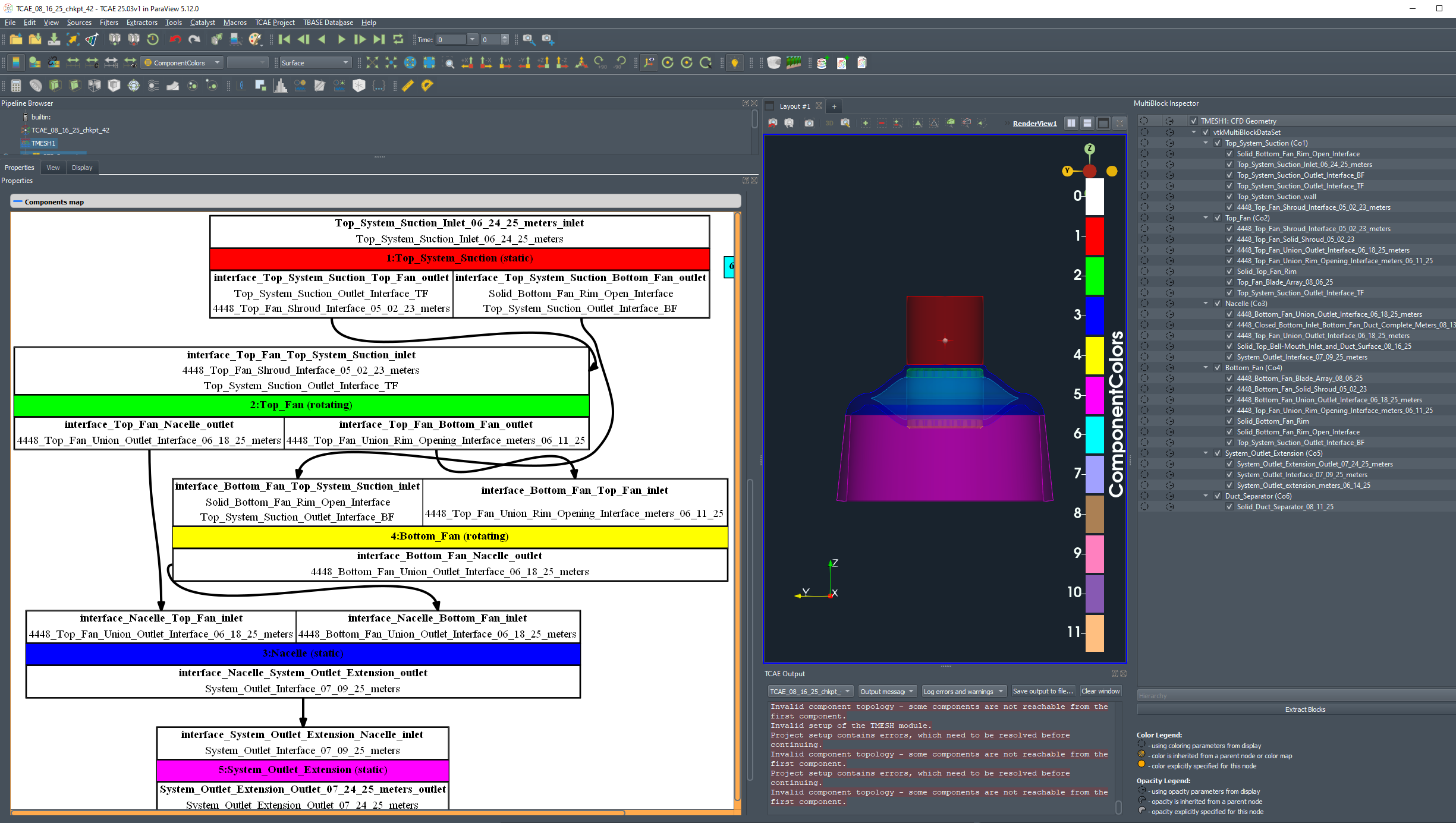
From the directory for the component named "Top_Fan", I copied and pasted an interface patch (.stl) into the directory for the component named "Hull__Inlet__Outlet", same file name, same type: "outletInterface" with the intention to prevent this from happening. It seems to me that in that instance it should be an inletInterface (just saying, I tried it that way...didn't help), Static Reference frame, another, different component.
Setup Problem is displayed upon selecting Check, listing the source, the copied patch in Top_Fan as the problem.
When I go into the Top_Fan component to connect the patch to the patch of same name in the Hull__Inlet__Outlet component, I don't see it listed as a choice, nor do any of the available listed options seem to work.
Changing the name slightly of the file in Hull__Inlet__Outlet had no effect.
How can I fix this? I'm stuck. Your help is appreciated in advance.
David
Mixing plane interface distorsion
- Post By Zacharie Prigent
- 10 months ago
- Post Type Public
Hi everyone,
I have a question concerning the mixing plane interface method : it seems to me that the method can generate numerical errors when reverse flow occurs on the interface.
To be more specific, I have a radial interface between the outlet of a centrifugal impeller and the inlet of its diffuser. On a specific zone of the interface, reverse flow occurs with a radial circumferential angle -180° < circAng < -90°, whereas on the rest of the interface, there is no reverse flow and 90° < circAng < 180°. In one of my former post on the forum, you confirmed to me that the weighted surface average of the circumferential angle might be distorted in this situation. It seems to me that the mixing plane method at the interface also encounter issues in this situation to estimate the value of circumferential angles for the inlet patch of the interface, in the strips where circAng oscillate between 90° < circAng < 180° and 180° < circAng < -90°. Indeed, I can see this kind of numerical errors when post-processing my simulations.
Do you have some recommendations to avoid this kind of problems ? For example, use specific configuration options, or different interface conditions ?
Thanks in advance !
Zacharie
Twin Centrifugal Fan Component Map
- Post By David Walden
- 10 months ago
- Post Type Public
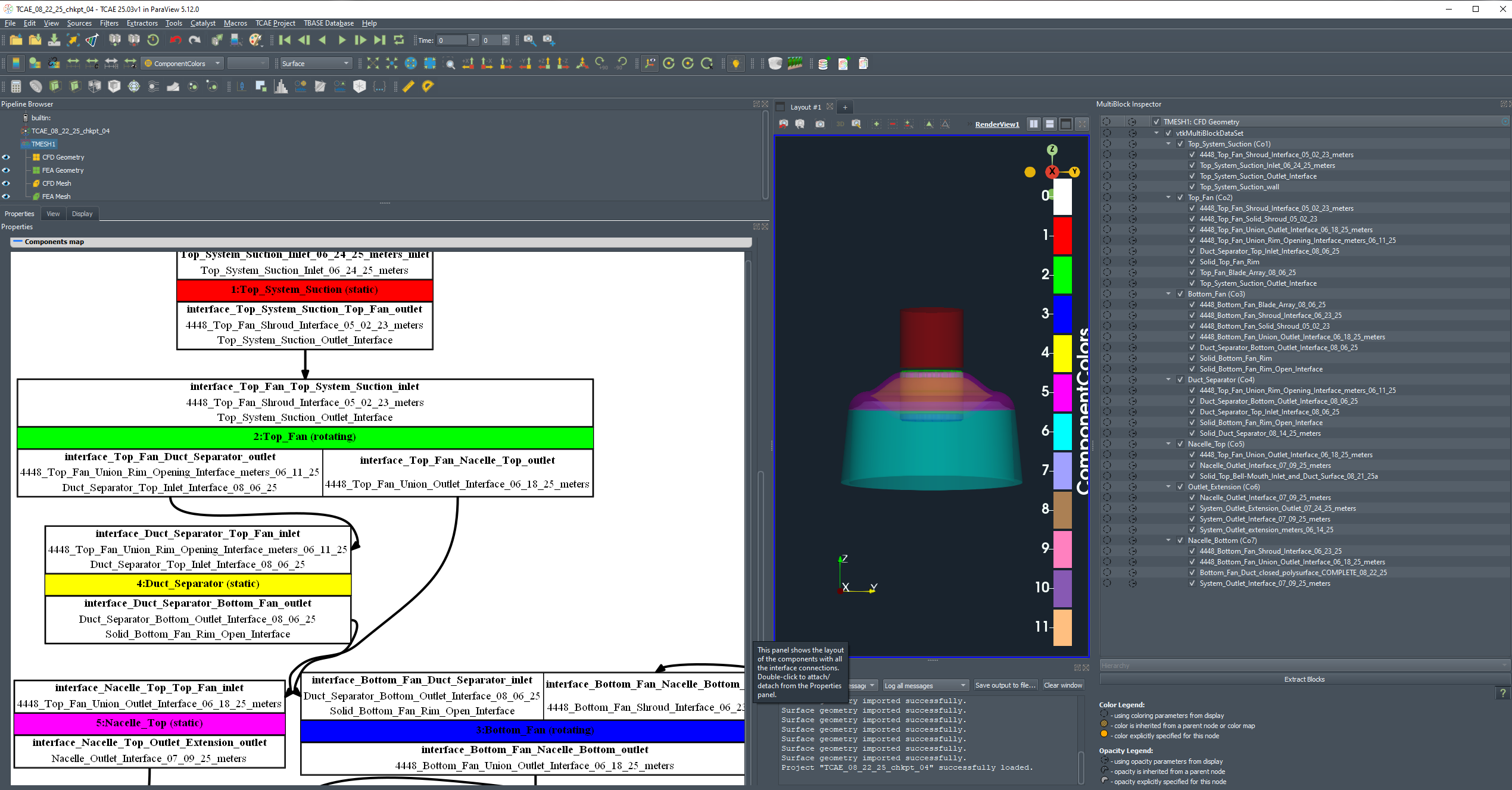
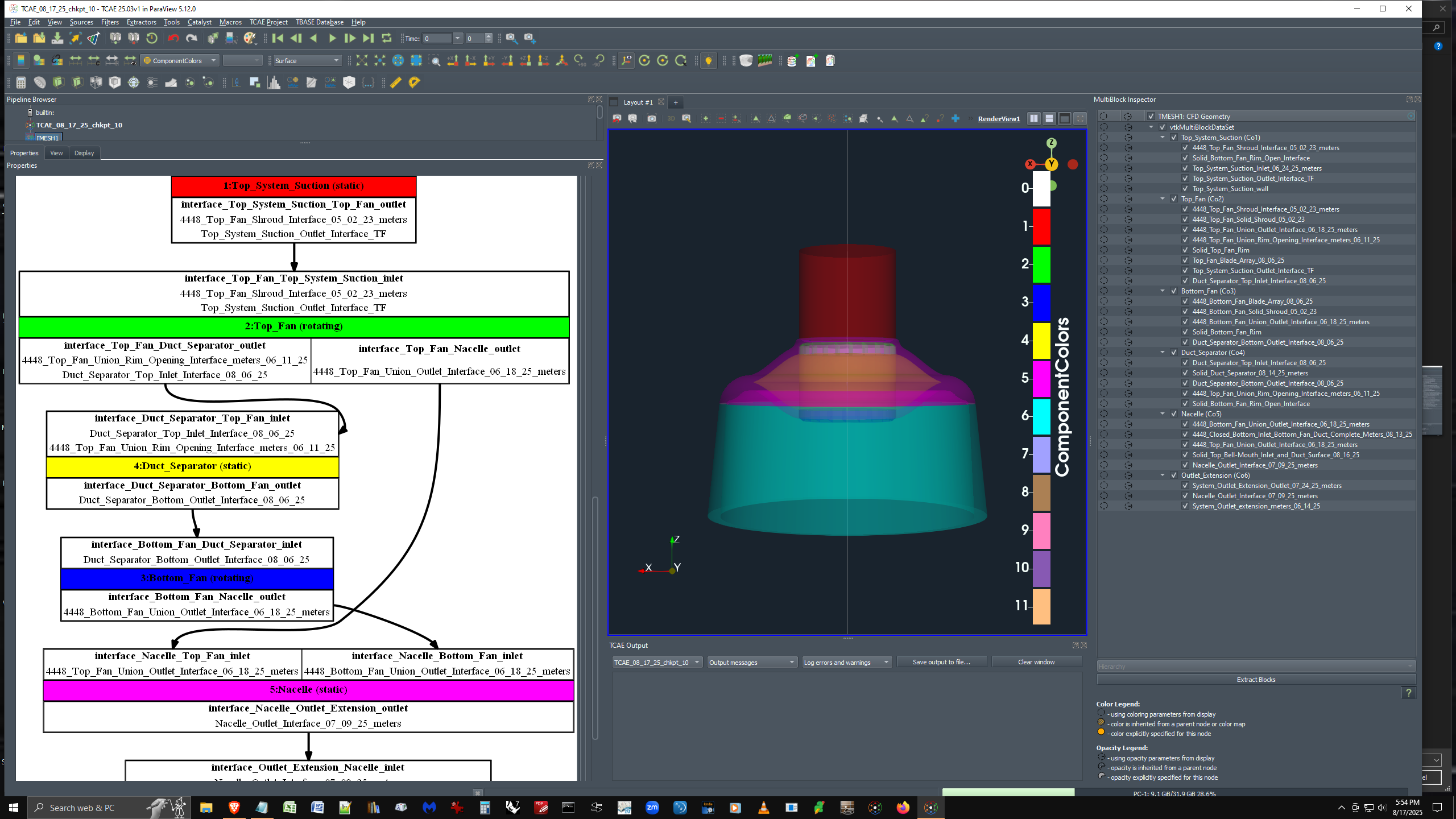
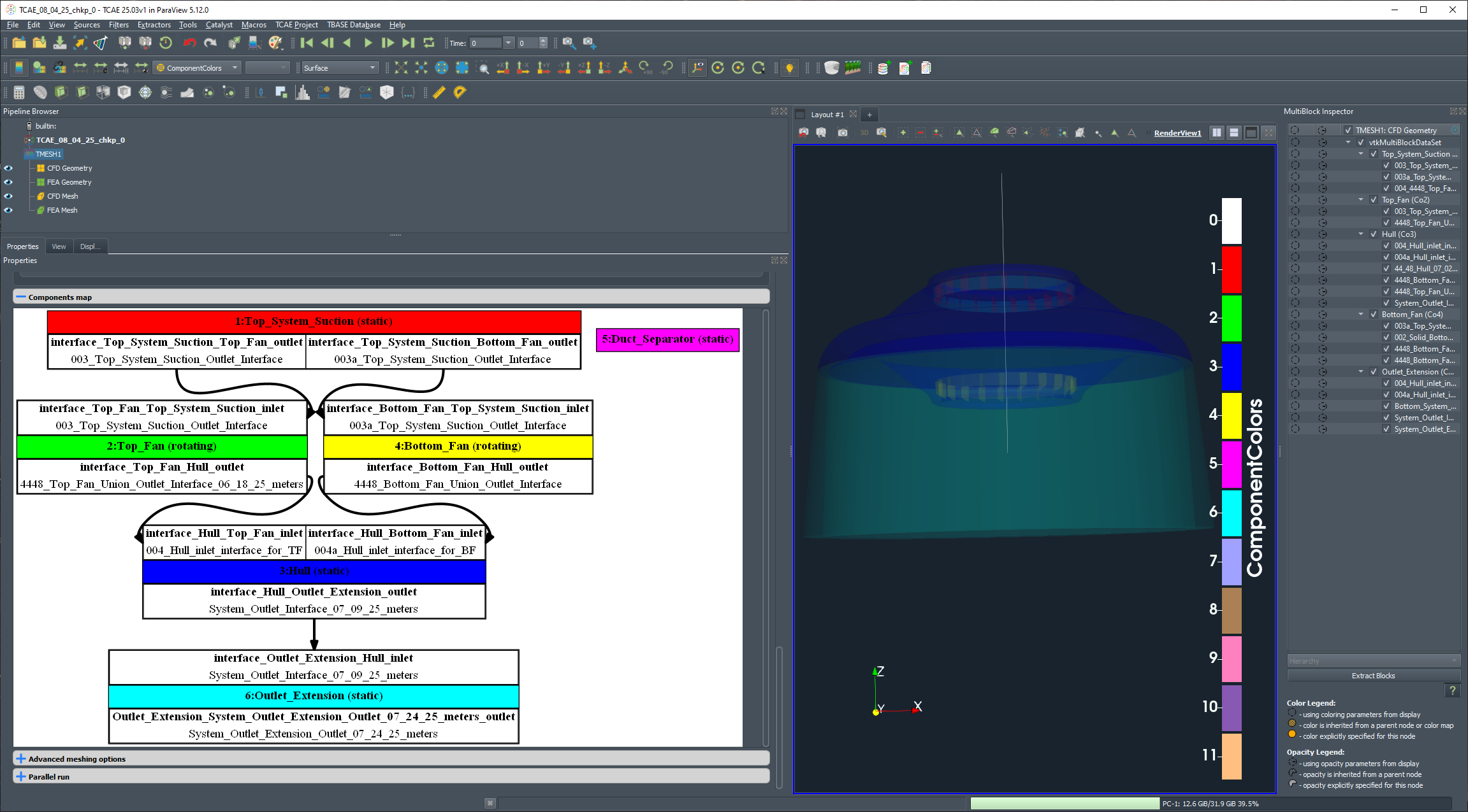
A common inlet at the top feeds two (identical) centrifugal fans. I tried to connect Top_System_inlet_interface (identical to but different in name as suction outlet interface) to serve double-duty as outlet interface to both the Top_Fan (rotating) AND Bottom_Fan (rotating).
It seemed that wasn't working so it occurred to me that connecting a copy of the object with another name might. Sure enough! It seems to have worked.
How would you have done it?
Question about snappyHexMesh and cellZone generation in OpenFOAM v2012
- Post By jiaming liu
- 10 months ago
- Post Type Public
Hi contributors,I sincerely appreciate your team's efforts in making your work publicly available online—it has been immensely helpful for OpenFOAM users and developers alike. After reading your article (Node266 - CFD SUPPORT), I followed the provided instructions to configure OpenFOAM to generate a cellZone using snappyHexMesh.
Unfortunately, the attempt was unsuccessful. The number of cells in both the cellZone and faceZones files turned out to be zero, and checkMesh.log confirms this issue. When I check the result via paraFoam, I also find that net0 ~ net4 contain no mesh—they are empty. This is not only contrary to my expectations, but also differs from the result described in the article.
I am using OpenFOAM v2012, and the net0 section in my snappyHexMeshDict was set up following the example from your webpage.
I’ve uploaded the relevant case below. I would greatly appreciate any guidance.
--------------------------------------------------------------------------------------------------
snappyhexmeshdict:
/*--------------------------------*- C++ -*----------------------------------*\
| ========= | |
| \\ / F ield | OpenFOAM: The Open Source CFD Toolbox |
| \\ / O peration | Version: v2012 |
| \\ / A nd | Website: www.openfoam.com |
| \\/ M anipulation | |
\*---------------------------------------------------------------------------*/
FoamFile
{
version 2.0;
format ascii;
class dictionary;
object snappyHexMeshDict;
}
// * * * * * * * * * * * * * * * * * * * * * * * * * * * * * * * * * * * * * //
#include "../varsSettings" //Include global variables
castellatedMesh true;
snap true;
addLayers false;//true;
geometry
{
floater
{
type triSurfaceMesh;
file "DeepCwindPlatform_heave.stl";
}
net1
{
type triSurfaceMesh;
file "Net1_improved_heave.stl";
}
net2
{
type triSurfaceMesh;
file "Net2_improved_heave.stl";
}
net3
{
type triSurfaceMesh;
file "Net3_improved_heave.stl";
}
net4
{
type triSurfaceMesh;
file "Net4_improved_heave.stl";
}
net0
{
type searchableBox;
min (-100 -50 -120);
max (100 50 -80);
}
refineFreeSurface_L1
{
type searchableBox;
min ($minX $minY -10);
max ($maxX $maxY 10);
}
refineFreeSurface_L2
{
type searchableBox;
min (#calc "$minX+$inLen+20" -70 -8);
max (#calc "$maxX-$outLen-20" 70 8);
}
refineFloater_L1
{
type searchableBox;
min (-51 -49 #calc "-30 + $decay_z + $offset_z");
max ( 37 49 #calc "22 + $decay_z + $offset_z");
}
};
castellatedMeshControls
{
maxLocalCells 100000;
maxGlobalCells 2000000;
minRefinementCells 0;
maxLoadUnbalance 0.10;
nCellsBetweenLevels 1;
features
(
{
file "DeepCwindPlatform_heave.eMesh";
level 4;
}
{
file "Net1_improved_heave.eMesh";
level 4;
}
{
file "Net2_improved_heave.eMesh";
level 4;
}
{
file "Net3_improved_heave.eMesh";
level 4; }
{
file "Net4_improved_heave.eMesh";
level 4;
}
);
refinementSurfaces
{
floater
{
level (4 4);//(5 5);
patchInfo
{
type wall;
// Optional group
// inGroups (meshedWalls);
}
}
net1
{
level (4 4);
cellZone net1Zone;
/* cellZoneInside inside;*/
faceZones net1fZone;
}
net2
{
level (4 4);
cellZone net2Zone;
/* cellZoneInside inside;*/
faceZones net2fZone;
}
net3
{
level (4 4);
cellZone net3Zone;
/* cellZoneInside inside;*/
faceZones net3fZone;
}
net4
{
level (4 4);
cellZone net4Zone;
/* cellZoneInside inside;*/
faceZones net4fZone;
}
net0
{
level (4 4);
cellZone net0Zone;
/* cellZoneInside inside;*/
faceZones net0fZone;
}
}
resolveFeatureAngle 45;//30;
planarAngle 30;
refinementRegions
{
refineFreeSurface_L1
{
mode inside;
levels ((1e-5 1)); //First entry here is distance, which will be ignored unless mode = distance
}
refineFreeSurface_L2
{
mode inside;
levels ((1e-5 2)); //First entry here is distance, which will be ignored unless mode = distance
}
refineFloater_L1
{
mode inside;
levels ((1e-5 2)); //First entry here is distance, which will be ignored unless mode = distance
}
/* net1*/
/* {*/
/* mode inside;*/
/* levels ((1e-5 3)); // STL 内部 refinement 到 level 4*/
/* }*/
/* net2*/
/* {*/
/* mode inside;*/
/* levels ((1e-5 3));*/
/* }*/
/* net3*/
/* {*/
/* mode inside;*/
/* levels ((1e-5 3));*/
/* }*/
/* net4*/
/* {*/
/* mode inside;*/
/* levels ((1e-5 3));*/
/* }*/
}
limitRegions
{
}
locationInMesh (-150 0 0);
allowFreeStandingZoneFaces true;//false;
faceZoneControls
{
}
locationsOutsideMesh ((100 100 100));
}
snapControls
{
nSmoothPatch 5;//3
tolerance 2.0;
nSolveIter 50;//30;
nRelaxIter 10;//5;
nFeatureSnapIter 20;//10;
implicitFeatureSnap false;//true;
explicitFeatureSnap true;//false;
multiRegionFeatureSnap false;
}
addLayersControls
{
relativeSizes true;
expansionRatio 1.25;
finalLayerThickness 0.64;
minThickness 0.1;
layers
{
floater
{
nSurfaceLayers 2;//3;
}
}
nGrow 0;
featureAngle 180;//180;
maxFaceThicknessRatio 0.5;//0.5;
nSmoothSurfaceNormals 1;
nSmoothThickness 10;
minMedialAxisAngle 90;
maxThicknessToMedialRatio 0.3;
nSmoothNormals 3;
slipFeatureAngle 30;
nRelaxIter 5;
nBufferCellsNoExtrude 0;
nLayerIter 50;
nRelaxedIter 20;
}
meshQualityControls
{
#include "meshQualityDict"
relaxed
{
maxNonOrtho 75;
}
nSmoothScale 4;
errorReduction 0.75;
}
mergeTolerance 1e-6;
// ************************************************************************* //
| ========= | |
| \\ / F ield | OpenFOAM: The Open Source CFD Toolbox |
| \\ / O peration | Version: v2012 |
| \\ / A nd | Website: www.openfoam.com |
| \\/ M anipulation | |
\*---------------------------------------------------------------------------*/
FoamFile
{
version 2.0;
format ascii;
class dictionary;
object snappyHexMeshDict;
}
// * * * * * * * * * * * * * * * * * * * * * * * * * * * * * * * * * * * * * //
#include "../varsSettings" //Include global variables
castellatedMesh true;
snap true;
addLayers false;//true;
geometry
{
floater
{
type triSurfaceMesh;
file "DeepCwindPlatform_heave.stl";
}
net1
{
type triSurfaceMesh;
file "Net1_improved_heave.stl";
}
net2
{
type triSurfaceMesh;
file "Net2_improved_heave.stl";
}
net3
{
type triSurfaceMesh;
file "Net3_improved_heave.stl";
}
net4
{
type triSurfaceMesh;
file "Net4_improved_heave.stl";
}
net0
{
type searchableBox;
min (-100 -50 -120);
max (100 50 -80);
}
refineFreeSurface_L1
{
type searchableBox;
min ($minX $minY -10);
max ($maxX $maxY 10);
}
refineFreeSurface_L2
{
type searchableBox;
min (#calc "$minX+$inLen+20" -70 -8);
max (#calc "$maxX-$outLen-20" 70 8);
}
refineFloater_L1
{
type searchableBox;
min (-51 -49 #calc "-30 + $decay_z + $offset_z");
max ( 37 49 #calc "22 + $decay_z + $offset_z");
}
};
castellatedMeshControls
{
maxLocalCells 100000;
maxGlobalCells 2000000;
minRefinementCells 0;
maxLoadUnbalance 0.10;
nCellsBetweenLevels 1;
features
(
{
file "DeepCwindPlatform_heave.eMesh";
level 4;
}
{
file "Net1_improved_heave.eMesh";
level 4;
}
{
file "Net2_improved_heave.eMesh";
level 4;
}
{
file "Net3_improved_heave.eMesh";
level 4; }{
file "Net4_improved_heave.eMesh";
level 4;
}
);
refinementSurfaces
{
floater
{
level (4 4);//(5 5);
patchInfo
{
type wall;
// Optional group
// inGroups (meshedWalls);
}
}
net1
{
level (4 4);
cellZone net1Zone;
/* cellZoneInside inside;*/
faceZones net1fZone;
}
net2
{
level (4 4);
cellZone net2Zone;
/* cellZoneInside inside;*/
faceZones net2fZone;
}
net3
{
level (4 4);
cellZone net3Zone;
/* cellZoneInside inside;*/
faceZones net3fZone;
}
net4
{
level (4 4);
cellZone net4Zone;
/* cellZoneInside inside;*/
faceZones net4fZone;
}
net0
{
level (4 4);
cellZone net0Zone;
/* cellZoneInside inside;*/
faceZones net0fZone;
}
}
resolveFeatureAngle 45;//30;
planarAngle 30;
refinementRegions
{
refineFreeSurface_L1
{
mode inside;
levels ((1e-5 1)); //First entry here is distance, which will be ignored unless mode = distance
}
refineFreeSurface_L2
{
mode inside;
levels ((1e-5 2)); //First entry here is distance, which will be ignored unless mode = distance
}
refineFloater_L1
{
mode inside;
levels ((1e-5 2)); //First entry here is distance, which will be ignored unless mode = distance
}
/* net1*/
/* {*/
/* mode inside;*/
/* levels ((1e-5 3)); // STL 内部 refinement 到 level 4*/
/* }*/
/* net2*/
/* {*/
/* mode inside;*/
/* levels ((1e-5 3));*/
/* }*/
/* net3*/
/* {*/
/* mode inside;*/
/* levels ((1e-5 3));*/
/* }*/
/* net4*/
/* {*/
/* mode inside;*/
/* levels ((1e-5 3));*/
/* }*/
}
limitRegions
{
}
locationInMesh (-150 0 0);
allowFreeStandingZoneFaces true;//false;
faceZoneControls
{
}
locationsOutsideMesh ((100 100 100));
}
snapControls
{
nSmoothPatch 5;//3
tolerance 2.0;
nSolveIter 50;//30;
nRelaxIter 10;//5;
nFeatureSnapIter 20;//10;
implicitFeatureSnap false;//true;
explicitFeatureSnap true;//false;
multiRegionFeatureSnap false;
}
addLayersControls
{
relativeSizes true;
expansionRatio 1.25;
finalLayerThickness 0.64;
minThickness 0.1;
layers
{
floater
{
nSurfaceLayers 2;//3;
}
}
nGrow 0;
featureAngle 180;//180;
maxFaceThicknessRatio 0.5;//0.5;
nSmoothSurfaceNormals 1;
nSmoothThickness 10;
minMedialAxisAngle 90;
maxThicknessToMedialRatio 0.3;
nSmoothNormals 3;
slipFeatureAngle 30;
nRelaxIter 5;
nBufferCellsNoExtrude 0;
nLayerIter 50;
nRelaxedIter 20;
}
meshQualityControls
{
#include "meshQualityDict"
relaxed
{
maxNonOrtho 75;
}
nSmoothScale 4;
errorReduction 0.75;
}
mergeTolerance 1e-6;
// ************************************************************************* //
Thank you very much in advance!
Best regards,
Liu Jiaming
The CFDSUPPORT ChatBot suggested steps for creating two meridional slices, one for each fan in TCAE
- Post By David Walden
- 10 months ago
- Post Type Public
The instructions are as follows:
To create two meridional slices, one for each fan in TCAE, follow these step-by-step instructions:
Load the Simulation Results: Open your TCAE project and load the results of your simulation for the fans.
Select the First Fan:
- In the Pipeline Browser, select the mesh or results corresponding to the first fan.
Add a Meridional Average Filter:
- Go to the Filters menu.
- Select "Turbomachinery" and then choose "Meridional Average."
I am not presently seeing any geometry in the Pipeline Browser, so, I tried double-clicking the individual STLs making up the component in CFD Mesh, (later realizing selecting multiple elements is not supported) then going to the Filters menu, selecting Turbomachinery, the option "Meridional Average." is greyed out, please see image.
I'm still at the beginning setup phase; loading geometry and tweaking types and interfaces. I have no results of any simulation to load. I have not tried to create a mesh yet. Is that (or something else) I need to do first besides read the manual?
Thanks in advance
David
I'm seeing two color bar legends in Reader View, one overlaying and obscuring the other.
- Post By David Walden
- 11 months ago
- Post Type Public
After reimporting surface geometry, I see that the legend for the color bar in Reader View has multiple color bar legends superimposed. Can I, should I hide one or the other?
If so, how?
Thanks,
David
Bottom_Fan_Bottom_Duct_Surface out of position (too low).
- Post By David Walden
- 11 months ago
- Post Type Public
I'm not wanting to re-import geometry, although that's most certainly what I'm preparing for at the moment. All the STLs were created using the _ExportWithOrigin command with World origin as basepoint in Rhino, so I'm scratching my head, as usual. Importing the offending object back into a "top" drawing, an assembly-of-all-parts model, and aligning it to it's exact position, then re-exporting it and replace the file having the wrong origin is what I'll try next.
Is there any easy way to manipulate objects once they've been imported?
Please see my comment, button at bottom right. Thanks.
Patch has not been found in just created mesh
- Post By Ashton Thomas
- 11 months ago
- Post Type Public
Mesh for component 1 was created incorrectly.
The patch(es) "1:Part_Studio_1_-_Outlet" has/have not been found in just created mesh.
There might be two reasons for that:
- Either the patch is so small, so the it was not possible to properly mesh it.
Check the patch visually, and also its meshing parameters.
- Second reason might be, that this patch is located outside the meshed geometry, and therefore cannot be meshed.
Again check the patch visually.
CFD meshing failed
I originally had this error on the Inlet patch, I don't know what I changed to correct that (nothing I believe)
The patch is not small, it appears water tight. It comes from a watertight model.
The patch is within the meshed geometry.
I've not had this error before, I've not struggled with meshing previously.
[Help Needed] Severe Contact Force Oscillations in Thrust Ball Bearing Model (Abaqus Implicit Dynamics)
- Post By Chengcheng WANG
- 11 months ago
- Post Type Public
Hello everyone,
I’m currently working on a thrust ball bearing simulation using Abaqus (implicit dynamics), and I’m encountering significant oscillations in the contact force (CFNM). I’d like to ask for advice on how to reduce or eliminate these oscillations.
🔧 Model Overview:
-
Analysis type: Implicit dynamic analysis
-
Simulation time: 0.01 second
-
Material: All parts are steel with elastic–plastic behavior and I add some density + damping
-
Ball settings: The balls are modeled as rigid bodies
-
Contact pair: Balls and inner ring
-
Contact formulation:
-
Surface-to-surface
-
Hard contact (normal behavior)
-
Friction coefficient: 0.2
-
Contact damping factor: 0.2
-
📌 Boundary and Loading Conditions:
-
The balls rotate around the inner raceway (orbital motion)
-
Each ball is subjected to a vertical force (toward the race)
-
The raceway is fully fixed at the bottom
-
Due to friction, the balls also spin around their own axes
❗ The Problem:
The CFNM (contact force in the normal direction) shows strong oscillations throughout the simulation. This instability leads to unreliable force results and makes it difficult to extract meaningful physical insights (see example plots below if needed).
✅ What I’ve Tried:
-
Using soft contact (reduced oscillations, but I need to retain stiffness accuracy → hard contact is necessary)
-
Applying smoothed initial loading using amplitude curves
-
Mesh refinement in the contact area
-
Adjusting contact damping (set to 0.2)
Unfortunately, none of these methods sufficiently reduced the oscillations.
❓ Questions:
-
Are there more effective ways to reduce or suppress contact force oscillations in implicit dynamic simulations?
-
Is my current contact damping value (0.2) too high or too low? Any empirical guidance?
Any advice, suggestions, or experience sharing would be greatly appreciated. I’m happy to provide figures or portions of the input file if helpful.
Thanks in advance!
overmesh with openfoam
- Post By pierre lecanu
- 11 months ago
- Post Type Public
How do you measure massflow rate through the system
- Post By Ashton Thomas
- 1 year ago
- Post Type Public
Hi All,
New user here. I've gone through the tutorials and forum but haven't found my answer. Asking the AI chat bot it says I need to do some scripting and change some files, which I don't believe. I feel the answer is more straight forward.
How do I measure the mass flow rate through my system? You can set the units for the report, but my report shows nothing of the sort. I'm sure there must be something simple like a button to calculate this?
TCFD repord failed
- Post By Jure Zilic
- 1 year ago
- Post Type Public
Hi,
I have a problem with report at the end?
Program made all 3000 iteration ( about 1.200.000 pcs), but at the end is allways problem with the report: (see picture below).
Thanks.