
tcae
CFD, OpenFOAM, ...

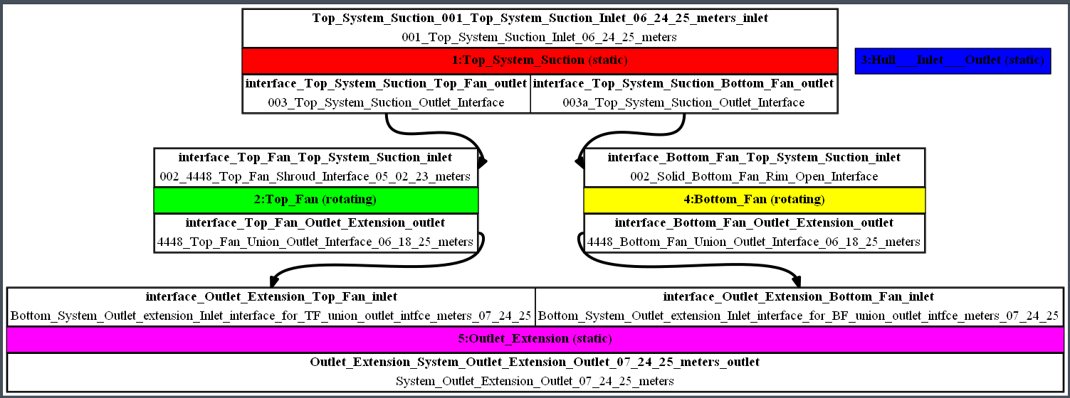
Just when I thought I had interfaces getting close to being set up with the project saved and closed....upon reloading the project, TCAE quits!
No warnings, no alerts. TCAE just quits.
In anticipation of posting this topic, I uploaded the project and STLs for your review. Please find download links in comments.
Please look for TCAE_07_27_25.zip for the project file and 4448_06_23_25_STL.zip for folders and patches.
Have you any ideas on how to proceed to fix the project?
Please let me know if you have any problems accessing or downloading the zip files.
Thanks in advance,
David
CFD, OpenFOAM, ...

The instructions are as follows:
To create two meridional slices, one for each fan in TCAE, follow these step-by-step instructions:
Load the Simulation Results: Open your TCAE project and load the results of your simulation for the fans.
Select the First Fan:
- In the Pipeline Browser, select the mesh or results corresponding to the first fan.
Add a Meridional Average Filter:
- Go to the Filters menu.
- Select "Turbomachinery" and then choose "Meridional Average."
I am not presently seeing any geometry in the Pipeline Browser, so, I tried double-clicking the individual STLs making up the component in CFD Mesh, (later realizing selecting multiple elements is not supported) then going to the Filters menu, selecting Turbomachinery, the option "Meridional Average." is greyed out, please see image.
I'm still at the beginning setup phase; loading geometry and tweaking types and interfaces. I have no results of any simulation to load. I have not tried to create a mesh yet. Is that (or something else) I need to do first besides read the manual?
Thanks in advance
David
CFD, OpenFOAM, ...
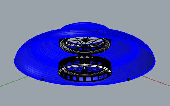
Please see my comments, below, for Fan and Duct Separator info.
Question: For the case with a closed bottom system inlet, is the Reference Frame of the Top Fan Open Rim interface, that's the second "surface" boundary that the incoming air encounters on it's way to join the other half; is it static, rotating, or freestream? Shared inlet air flows through it to the inlet of the bottom fan. How about it's type?
Same question for bottom fan except, because it is upside-down compared to the top fan; what is the reference frame of the Bottom Fan Open-Rim Interface? While we're at it, how about the Bottom Fan Shroud Interface? Closed bottom inlet, remember?; are they static, rotating, or freestream? Type?
From the shared inlet at the top of an axi-symmetric radial discharge duct, aka Volute or Hull, one-half of the flow first enters between the Top Fan Shroud and Rim, then blade passages, exits the fan, rides a cosine curve down to join the other half geometrically mirrored about the X-axis, which has become the Bottom Fan discharge, combines radially without colliding too much, then downward smoothly toward axial, but not exactly.
I have an idea for dynamic stability, could be combined with distance between cg and center-of- lift asymmetry.
Closed Bottom Duct Surface and Duct Separator not shown for clarity. No bottom inlet opening for first simulation case. System outlet is a 0.83 [m] outside diameter annulus of appropriate area for combined fan discharge.
The Fans: each identical, one-piece solid poly-surface Boolean union of rim, shroud, and blade array has open rim, no hub, mounted to a 0.315 [m] OD carbon fiber rim bicycle wheel.
Thanks in advance.
David
TCAE Tech Support

Hi,
I have a problem with report at the end?
Program made all 3000 iteration ( about 1.200.000 pcs), but at the end is allways problem with the report: (see picture below).

Thanks.
TCAE Tech Support
Hi,
I have a problem with report at the end?
Program made all 3000 iteration ( about 1.200.000 pcs), but at the end is allways problem with the report: (see picture below).
Thanks.
CFD, OpenFOAM, ...

Hi,
I'm a new user of TCAE-Lite.
I've setup a pump case and the "check" button says the case has been setup correctly. However it fails to mesh.
The same error occurs when running the f1 tutorial case.
Any advice would be appreciated,
Thanks,
Tom
TCAE Tech Support


General Discussion

TCAE-Lite is designed for those with limited budgets.
Over 50 man-years of consistent development on top of open-source condensed in unlimited software at the cost of a daily cup of coffee.
https://www.cfdsupport.com/tcae-lite.html
Regarding the TCAE-Lite, it's our recipe for those with extremely limited budgets (to avoid giving them a license completely for free) who can dedicate their time instead. Professionals should still consider the full-blooded TCAE.
Information about simulation software TCAE-Lite:
- TCAE-Lite is a simplified version of TCAE which includes software modules TMESH and TCFD.
- TCAE-Lite is designed primarily for individuals to make this unique technology available to everyone.
- TCAE-Lite is a standalone and complete CFD software without any hidden limitations or software dependencies.
- TCAE-Lite has one universal simulation template general for all types of simulations.
- The license is provided to individual users.
- Technical support is provided via cae-forum.online.
- TCAE-Lite will be further developed as a general GUI for open-source CFD simulations.
- Freely available resources: case studies, benchmarks PDF, webinars, training PDF, manual PDF
- Here is the pdf where you can find more details (including pricing structure): https://www.
cfdsupport.com/download/CFD- SUPPORT-TCAE-Price-List.pdf - TCAE-Lite doesn't include any engineering consultancy or personal training.
- For administrative reasons, TCAE-Lite does not have a trial version.
- Its monthly cost is as low as one dinner out.
- All necessary information is available on our website: https://www.
cfdsupport.com/tcae-lite.html
hashtag#CFD hashtag#Simulation hashtag#FluidDynamics hashtag#FlowVisualization
TCAE Tech Support

I am looking to simulate the power output of an in pipe axial turbine, I don't have any experience in CFD simulations and I've decided to brake down the project into 3 parts, first I am going to simulate just the pipe in which the turbine is going to be housed, then a static state with the turbine in the pipe, and finally setup the rotation of the turbine.
I've made a quick 3D model of the pipe and I tried copying the setup from the pipe example, I ran into a problem where the mesher consumes all the available RAM on the computer and locks it up, I assume the STL mesh has a hole somewhere but I couldn't find it, I've had issues before with glitches in STL meshes made in Rhinoceros 3D, the modeling program I used, so I decided to recreate the pipe example with the STLs from the example, and that meshed successfully, but I got an error in the TCFD part "TCFD calculation failed. Please consult the chapter 'Rescue list' in the TCAE Manual for possible reasons of the failure.", I couldn't find the Rescue list chapter in the manual online.
Also the TCAE Output gives this error:
"Application decomposePar failed.
For detailed information check error log at: "C:\Users\Name\Desktop\CFD Test\CFD_test\simulationRun1\TCFD\logRun\solve-err-decomposePar-stationary-1.log"".
And in that log file is:
"--> FOAM FATAL IO ERROR:
Cannot find patchField entry for Co1_pipe-wall_wall
file: C:/Users/Name/Desktop/CFD Test/CFD_test/simulationRun1/TCFD/stationary/0/nut/boundaryField from line 32 to line 54.
From function void Foam::GeometricField<Type, PatchField, GeoMesh>::Boundary::readField(const Foam::DimensionedField<TypeR, GeoMesh>&, const Foam::dictionary&) [with Type = double; PatchField = Foam::fvPatchField; GeoMesh = Foam::volMesh]
in file /opt/OpenFOAM-dev/src/OpenFOAM/lnInclude/GeometricBoundaryField.C at line 184.
FOAM exiting"
Attached is a rough diagram of how will the setup work.
I don't have an idea what to try next, and would be thankful for any assistance.
TCAE Tech Support

Hello,
The values of axial and radial forces obtained from the TCAE software report for my pump(Q= 310 m^3/h, H= 54 m, n=1450 rpm) give unreasonable results. The main cause is related to which part or parameter?
Thank you very much.